The Following tips and examples should be helpful to those considering or just getting started with Multi-Axis Milling toolpaths.
Tip #1: Use “clean” geometry.
Garbage in = Garbage out. Multi-axis calculations are complex, so it is essential to drive multi-axis toolpaths with as simple and robust geometry as possible. For example, the part below has two slots. They are identical except for the circular cutouts in slot 1. In this case it is better to choose the slot 2 (without the cutouts) because it the floor surface is simpler. The toolpaths can be Pattern copied to machine the other slot.
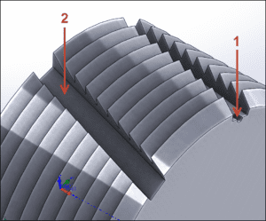
Figure 1: Pick simplest features
You could also Suppress the cutout features before creating the multi-axis toolpaths to rough and finish the slot. [Use the Protect option to lock those toolpaths before un-suppressing the slots so your toolpaths will not regenerate.]Another solution might be to create a Surface to drive a multi-axis toolpath. Notice how, when the surface lies right on the model face it is replicating, the surface looks splotchy (Fig. 2).
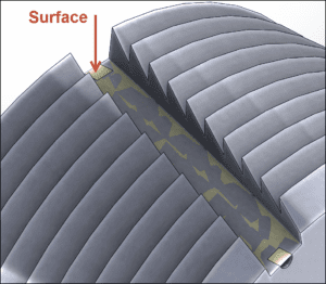
Figure 2: Create drive surface
Tip #2: Contour Driven is Often Better Than Surface Driven for Multi-Axis Swarf
Swarf milling mills with the side of the tool to machine a feature -tilting the tool to maintain contact with the wall. Swarf toolpaths can be Surface or Contour driven. Contour is often a more reliable method for creating efficient Swarf toolpaths because it is simpler.
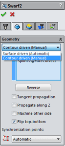
Figure 3: Swarf Geometry Options
In this example (Fig. 4), the wall surface includes a saw-tooth shape. Synchronizing the bottom and top edges of this face to produce a smooth path is difficult. Contour is a better choice but, while there is a lower rail (the edge between wall and floor), there is no simple upper rail to select. One solution is to create a simple curve using (in SolidWorks) Tools, Sketch Tools, Face Curves or (depending on the situation), Insert, Curve, Projected to project a Sketch onto a surface(s)).
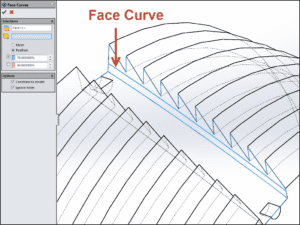
Figure 4: Face Curve created to drive Swarf toolpath
Tip #3: Simplify The Stock
This part is turned on a lathe before milling. The actual stock looks more like the cross-section view below (Fig. 5). All we are concerned about on this part though is the slot on OD. Modeling the stock using the Cylindrical option, rather than a more complex revolved solid, both speeds calculations and increases toolpath reliability.

Figure 5: Simplified Stock
Tip #4: Consider Increasing Cut Tolerances
The default toolpath tolerance in HSMWorks is .0004 inches. Depending on the quality and shape of the underlying geometry, you may want to open this tolerance. If the model is very large or complex it is a good idea to begin with looser tolerances anyway because toolpaths will generate faster. You can then go back and increase the tolerances before final post processing to meet your machining tolerance requirements..
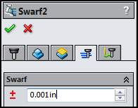
Figure 6: Cut Tolerance
Tip #5: Don’t Forget the “Use 4-Axis” Setting
When using Multi-axis toolpaths on a single-axis rotary table machine, don’t forget to turn on Tool Orientation and select the “Use 4-Axis” option. This lets HSMWorks know that your machine is not capable of rotating about a secondary rotary axis. If this option is not selected then an A-Axis post processor will generate the following error if it detects even the smallest B-axis motion, “Error: Direction is not supported for machine configuration.”
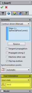
Figure 7: Use 4-Axis
A lot of 5-axis machining is actually positioning (3+2) work that HSMWorks excels at. Much of the rest is relatively simple multi-axis milling that is readily supported by the Swarf and Multi-axis Curve features in our HSMWorks Premium software. We make multi-axis machining as simple as it gets. For many applications, HSMWorks today provides great tools for supporting your multi-axis machining needs.
The following resources are available to help you get started with multi-axis machining: