Custom shaped milling tools in HSMWorks are collectively know as Form Mill tools, and can be created from a sketch or revolved solid saved in a separate SolidWorks part file.
To create a form mill tool, follow these steps:
- Create a new SolidWorks part.
- Create a sketch with a single closed contour that represents the cross section of the tool.
- Create a Revolved Boss/Base feature from the sketch.
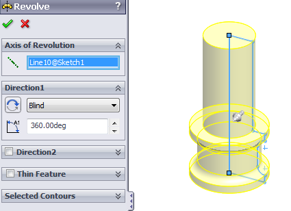
A revolved boss/base feature in a SolidWorks part, suitable for creating a Form Mill tool.
- Optional:Create a reference point feature from the Reference Geometry menu.
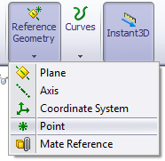
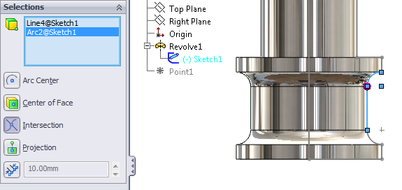
Creating a reference point feature at position that can be used for compensating the toolpath.
- Save the part file.
- Open the HSMWorks Tool Library.
- Create a new mill tool by pressing the New Mill Tool button.
- Choose “Form Mill” from the Type drop down menu.
- Press Import File…
- Browse to and select the tool file you saved before.The sketch profile will be loaded as the profile for the form mill, and previewed as shown here.
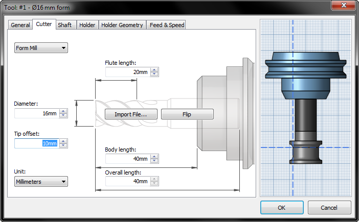
The Form Mill dialog with preview. The dotted lines show the toolpath compensation
point, which is controlled by the diameter and tip offset.
Using the tool is done similarly to all other tools, keeping in mind that the toolpath is created in relation to the compensation point defined by the diameter and tip offset.
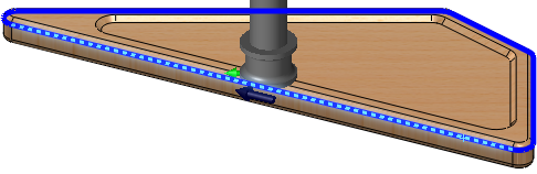
Selected geometry for a 2D Contour using the tool with compensation point as shown above.
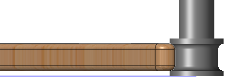
Simulating with the custom shape form mill tool.
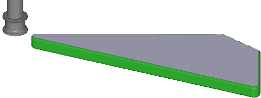
Stock simulation with the custom shape form mill tool.