There are two ways to use the HSMWorks chamfering feature, depending on whether the CAD model already has the chamfering as a feature or not.

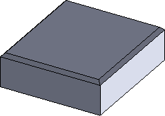
Left: CAD model with no chamfering / Right: CAD model with chamfering feature
In both cases, you can use the 2D contour strategy to chamfer the model.
First, define and selecting a chamfer mill tool. This will automatically enable the Chamfer option in the 2D Contour parameter group:
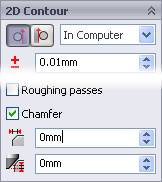
Chamfer parameters
 Chamfer Width
The (additional) width of the chamfer. For edges that are not already chamfered this will be the final width of the chamfer. For chamfered edges this will be an additional offset, similar to using negative radial stock to leave.
 Chamfer Tip Offset
This is added to the toolpath depth, while keeping the tool in contact with the selected edge by adjusting the toolpath radial offset.
With these two parameters we can handle both types of CAD models.
In the case where the edges are not chamfered we set the width to the wanted amount, and then adjust the tip offset depending on the size of the tool.
If the model has already been chamfered, the easiest way is to select the lower edge of the chamfer. This will put the tool chamfer corner at this position and we only need to adjust the tip offset if we want to go some distance below the lower edge.
Notice:Chamfering with ball and bull cutters is supported.